
Due to its advantages of high hardness, high strength, low density and excellent mechanical properties, superrigid aluminum alloy is widely used in aviation, aerospace, rail transit and automobile.In aviation and automobile manufacturing industries, the dimensional accuracy and surface roughness of structural parts are highly required, while in actual PCD tool cutting production of superrigid aluminum alloy, the selection of processing parameters mostly depends.
There are many researches on the machining of superhard alloy with carbide tool or the machining of ordinary aluminum alloy with PCD tool, but there are few researches on the cutting performance of superhard alloy with PCD tool.Therefore, it is necessary to conduct experimental research on the turning of superhard aluminum alloy with PCD tool, and analyze the cutting performance such as cutting force and surface roughness of turning AL7075-T6 with PCD tool through cutting test.
Material parameters of workpiece and tool
(1) Material parameters of the workpiece
The workpiece is al7075-T6 aluminum alloy bar material, Al7075 is the common type of 7XXX series aluminum alloy, T6 refers to the aluminum alloy 7075 after solid solution treatment of artificial aging process. he chemical composition and some physical and mechanical properties of AL7075-T6 are shown in Table 1 and Table 2.
Table 1 Chemical composition of Al7075 aluminum alloy (%)
|
Aloying element |
Zn |
Mg |
Cu |
|
Content |
5.0~6.1 |
2.1~2.9 |
1.2~2.0 |
|
Aloying element |
Cr |
Si |
Fe |
|
Content |
0.18~0.28 |
≤0.40 |
1≤0.50 |
Table 2 Partial physical and mechanical properties of AL7075-T6 at room temperature
|
Density (g/cm³) |
Elasticity modulus (GPa) |
Tensile Strength (MPa) |
Yield strength (MPa) |
Hardness (HBS) |
Thermal conductivity (W/m·K) |
Thermal expansivity (%) |
Extend rate (%) |
Poisson's ratio |
|
2.81 |
71.7 |
572 |
503 |
150 |
130 |
23.6 |
11 |
0.33 |
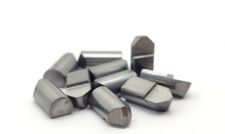
2) Material parameters of the cutter
Due to the aluminum alloy cutting light, the tool wear is not serious, in the production of most of the choice of more economical PCD welding tool.The cutter rod material is 45 steel, the blade base material is carbide, and the blade material is PCD composite sheet.The main physical properties of PCD materials are shown in Table 3.
Table 3 Main physical properties of PCD materials
|
Hardness (HB) |
Yield strength (MPa) |
Compressive strength (MPa) |
Elasticity modulus (GPa) |
Thermal conductivity (W/(m·K) |
Friction coefficient
|
|
105 |
210~490 |
1500~2500 |
9~10.5×10² |
700 |
0.06~0.13 |
Cutting performance test
(1) Test conditions
Sb-cnc ultra-precision turning and milling compound center was used in the test, and customized PCD brazing lathe tool was selected. The cutting force measurement system was composed of 9119AA2 type tridirectional piezoelectric micro precision force measuring plate, 5167A charge amplifier, Sirius-8xACC data collector and computer (from right to left in Figure 1). Mitutoyosj-201 roughness tester was used to measure the surface roughness of the workpiece.
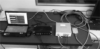
FIG. 1 Cutting force measurement system
(2)Testing scheme
In actual production, PCD tools are mostly used for finishing, and reducing the back draft will significantly reduce the cutting force of PCD tools in turning superhard aluminum alloy. Therefore, a smaller back draft is selected in the test.Fine car should be to ensure the quality of processing, in general, the smaller the feed, the lower the surface roughness of the processed workpiece.Due to high hardness, good wear resistance, good thermal conductivity and low friction coefficient, PCD is suitable for high-speed machining, so the test chooses a higher cutting speed.High cutting speed can inhibit the formation of chip tumor and improve the surface quality of the workpiece.Increasing cutting speed can improve machining efficiency.The dry cutting method is adopted in the test, and the increase of cutting speed can make most of the cutting heat be taken away by the chip, thus reducing the cutting temperature.
According to the simulation results, the increase of tangential force and radial force is relatively slow when the back draft is increased within the range of 0.05 ~ 0.2mm.When the back draft is increased in the range of 0.2 ~ 0.4mm, the cutting force increases relatively quickly and has a linear relationship with the back draft.Therefore, the range of back draft in the test is 0.05 ~ 0.2mm, which is the best.In order to comprehensively consider the influence of cutting parameters on PCD tool turning AL7075-T6, establish BP neural network prediction model and obtain sufficient sample Numbers, a total of 64 groups of three-factor and four-level full-factor tests were used. The test factors and level values are shown in Table 4.
Table 4. Factor levels of full-factor test
|
Factor level |
A Back cutting depth ap (mm) |
B Feed rate f(mm/r) |
C Cutting velocity v(m/min) |
|
1 |
0.05 |
0.025 |
300 |
|
2 |
0.1 |
0.05 |
600 |
|
3 |
0.15 |
0.075 |
900 |
|
4 |
0.2 |
0.1 |
1200 |
(3) Analysis of test results
The three-way dynamic cutting force data obtained by cutting force measurement system in turning test are real-time cutting forces.In order to obtain the effective cutting force value, data processing is needed to obtain the root mean square value of the three-way dynamic cutting force in the stable cutting process.When measuring the roughness of the workpiece's outer circle surface for each group of tests, in order to reduce the measurement error of surface roughness, one roughness measurement is conducted on the radial cross section every 72°. The entire outer circle is measured for 5 times in total, and the roughness average value of the 5 measurements is calculated.Due to the large number of test data, only partial cutting force and surface roughness results of turning tests are listed, as shown in Table 5.
Table 5 Full factor test results
|
Test number |
Back cutting depth ap (mm) |
Feed rate f(mm/r) |
Cutting velocity v(m/min) |
Radial force Fp(N) |
Tangential force Fc (N) |
Axial force Ff (N) |
Resultant force F(N) |
Roughness Ra(μm) |
|
DOE 01 |
0.05 |
0.025 |
300 |
1.09 |
1.06 |
0.12 |
0.525 |
0.092 |
|
DOE 02 |
0.05 |
0.025 |
600 |
1.15 |
1.06 |
0.20 |
1.577 |
0.092 |
|
DOE 03 |
0.05 |
0.025 |
900 |
1.06 |
1.08 |
0.20 |
1.526 |
0.106 |
|
DOE 04 |
0.05 |
0.025 |
1200 |
1.40 |
1.19 |
0.30 |
1.862 |
0.084 |
|
DOE 05 |
0.05 |
0.050 |
300 |
1.25 |
1.61 |
0.16 |
2.045 |
0.166 |
|
DOE 06 |
0.05 |
0.050 |
600 |
1.29 |
2.74 |
0.22 |
3.036 |
0.166 |
|
DOE 07 |
0.05 |
0.050 |
900 |
1.22 |
1.69 |
0.26 |
2.100 |
0.170 |
|
DOE 08 |
0.05 |
0.050 |
1200 |
1.62 |
1.92 |
0.27 |
2.527 |
0.196 |
|
DOE 09 |
0.05 |
0.075 |
300 |
1.46 |
2.13 |
0.19 |
2.589 |
0.326 |
|
DOE 10 |
0.05 |
0.075 |
600 |
1.45 |
2.32 |
0.23 |
2.746 |
0.296 |
|
DOE 11 |
0.05 |
0.075 |
900 |
1.39 |
2.28 |
0.26 |
2.683 |
0.330 |
|
DOE 12 |
0.05 |
0.075 |
1200 |
1.85 |
2.49 |
0.35 |
3.122 |
0.324 |
|
DOE 13 |
0.05 |
0.100 |
300 |
1.67 |
2.65 |
0.22 |
3.140 |
0.456 |
|
DOE 14 |
0.05 |
0.100 |
600 |
1.65 |
2.81 |
0.23 |
3.267 |
0.516 |
|
DOE 15 |
0.05 |
0.100 |
900 |
1.56 |
2.87 |
0.26 |
3.277 |
0.456 |
|
DOE 16 |
0.05 |
0.100 |
1200 |
2.05 |
3.20 |
0.28 |
3.811 |
0.476 |
|
DOE 17 |
0.10 |
0.025 |
300 |
1.41 |
1.25 |
0.25 |
1.901 |
0.100 |
|
DOE 18 |
0.10 |
0.025 |
600 |
1.52 |
1.84 |
0.33 |
2.409 |
0.112 |
|
DOE 19 |
0.10 |
0.025 |
900 |
1.38 |
1.78 |
0.31 |
2.274 |
0.108 |
|
DOE 20 |
0.10 |
0.025 |
1200 |
1.77 |
1.99 |
0.35 |
2.686 |
0.094 |
Through data analysis, relevant conclusions are drawn as follows:
1.The variation of cutting force with cutting parameters
It can be seen from Table 5 that, with the increase of the back draft, the three-way cutting force gradually increases, the tangential force is greater than the radial force, and the radial force is greater than the axial force.The increase of back draft makes the cutting area increase and the length of cutting edge increases accordingly, so the cutting force must increase.With the increase of feed, the three-way cutting force increases gradually, the tangential force is greater than the radial force, and the radial force is greater than the axial force.The tangential force is most significantly affected by the amount of feed.The radial force increases slowly with the feed rate.The increase in axial force is modest.
2.The variation of surface roughness with cutting parameters
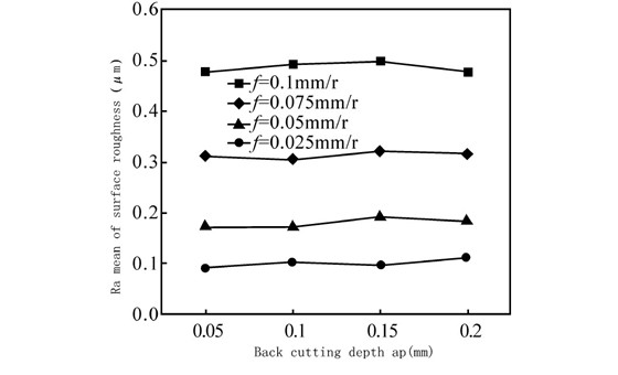
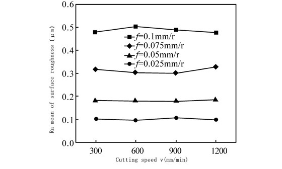
According to the test results of surface roughness, the interaction diagram of surface roughness Ra with respect to cutting parameters was drawn, as shown in Figure 2.In FIG. 2A, the four broken lines representing different feeds are parallel to each other, indicating that there is no interaction between the back feed and feed.The mean value of surface roughness is different for different feed, which indicates that the surface roughness value has a great correlation with the feed value.Figure 2B is similar to Figure 2A. Four broken lines representing different feeds are basically parallel, indicating that there is no interaction between cutting speed and feed.In FIG. 2C, the four broken lines representing different cutting speeds are not only parallel, but also close to each other in terms of surface roughness, indicating that there is no interaction between backdraft and cutting speed, and the impact of cutting speed on surface roughness is not obvious.
(a) Back cutting depth (ap) with feed rate (f)
(b) Cutting speed (v) with fade rate (f)
(c) Back cutting depth (ap) with cutting speed (v)
.jpg)
The above analysis shows that there is no interaction between surface roughness and backdraft, feed and cutting speed. According to the roughness results in Table 5, the main effect diagram of surface roughness on cutting parameters, as shown in Figure 3, is drawn. In the figure, the meanings of factors A, B, C and levels 1, 2, 3 and 4 are shown in Table 4.It can be seen that the back draft and cutting speed have little influence on the surface roughness. The influence of feed on surface roughness is obvious. With the increase of feed, the surface roughness increases obviously. The larger the feed, the larger the increase of surface roughness.
With tungsten carbide prices soaring 200%+, PCD & CBN become cost-effective alternatives. Moresuperhard provides high-quality PCD/CBN blanks, grinding wheels & grinders to help manufacturers reduce costs and improve efficiency.
Learn the technical characteristics, advantages, disadvantages and applicable working conditions of standard TSP and nickel-based coated TSP. Compare their performance differences and master the selection skills for drilling, cutting and grinding scenarios.
Add: Zhongyuan Rd, Zhongyuan District, Zhengzhou, 450001, Henan, China
Tel: +86 17700605088