

The face and the flank are pain surfaces, the cutting edge can be assumed to be a line. These surfaces and the edges are inclined with respect to some reference plan or line. The inclinations are called tool angles.
These angles are defined by various names. They are provided for various purposes. Consider the case of the face abgf, as shown in Fig. 9.12. It is a plane surface no doubt, but can have some inclinations. This surface may be parallel to the base or say to horizontal surface, or it can be inclined upward or downward with respect to the horizontal plane. Again it may have inclination sideward also. So in general the face can have two inclinations simultaneously, backward and sideward. Similarly the flank (Principal flank abed or auxiliary flank adef) can have two inclinations.
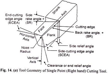
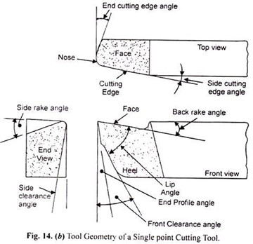
For efficient machining operation, the cutting tool must be provided with necessary tool angles. A tool with proper geometry (cutting edge and tool angles) cuts the metal effectively. Therefore reducing the chattering, breaking of the tool with less heat generation. Fig 9. 14. (a) and (b) shows a single point cutting tool with various cutting edges and tool angles.
From the geometry of cutting tool the various cutting tool angles are:
Rake Angle (α):
(a) Black rake angle.
(b) Side rake angle.
Clearance or Relief Angle (γ):
(a) End clearance relief angle.
(b) Side clearance relief angle.
Cutting Edge Angle:
(a) End cutting edge angle.
(b) Side cutting edge angle.
(i) Back Rake Angle:
It is the angle between the face of the tool and plane parallel to its base. It is also known as front rake angle or top rake angle.
(ii) Side Rake Angle:
It is the angle between the face of the tool and the shank of the tool.
(iii) End Clearance (Relief) Angle:
It is the angle between the front surface of the tool and a line normal to the base of the tool. It is also known as front clearance angle.
(iv) Side Clearance (Relief) Angle:
It is the angle between the side surface of the tool and a line normal to the base of the tool.
(v) End Cutting Edge Angle:
It is the angle between the end cutting edge of the tool and a line perpendicular to its shank.
(vi) Side Cutting Edge Angle:
It is the angle between the side cutting edge of the tool and shank of the tool.
(vii) Nose Radius:
Nose radius is one which connects the side and end cutting edge. Now, we will discuss the functions and effects of cutting tool angles on cutting process.
Functions of Back Rake Angle:
(a) It helps to control the chip flow in a convenient direction.
(b) It reduces the cutting force required to shear the metal and consequently helps to reduces power requirements and increase tool life.
(c) It also helps counteract the pressure against the cutting tool from the work by pulling the tool into the work.
(d) It provides keenness to the cutting edge and improves the surface finish.
Functions of Side Rake angle:
(a) It performs similar functions as performed by back rake angle.
(b) Side rake angle along with back rake angle controls the chip flow direction.
(c) It partly counteracts the resistance of the work to the movement of the cutter.
(d) For example, brass requires a back and side rake angle of almost 0°, while aluminum uses a back rake of 35° and a side rake of 15°.
Functions of End Clearance (relief) Angle:
(a) It allows the tool to cut freely without rubbing against the work surface.
(b) This angle varies from 0° to 15°, and usually 8°.
(c) Excessive relief angle reduces strength of the tool.
Functions of Side Clearance (relief) Angle:
i. It avoids the rubbing of flank against the work piece when the tool is fed longitudinally.
ii. This angle is 6° to 10° for steel, 8° for aluminum.
iii. It maintains that no part of the tool besides the actual cutting edge can touch the work.
Functions of End Cutting Edge Angle:
i. It avoids rubbing between the edge of the tool and workspace.
ii. It influences the direction of chip flow.
Functions of Side Cutting Edge Angle:
i. Increase in side cutting edge angle tends to widen and thin the chip.
ii. An excessive side cutting edge angle redirects feed forces in radial direction which may cause chatter.
Functions of Nose Radius:
i. A sharp point at the end of tool is undesirable, because it is highly stressed, short lived and leaves groove in the path of cut.
ii. Therefore Nose Radius is favourable for long tool life and good surface quality.
iii. It affects the tool life, radial force, and surface quality of work piece.
iv. If nose radius is too large chatter will occur.
v. There is an optimum value of the nose radius at which the tool life is maximum.
vi. If the nose radius exceeds optimum value, the tool life decreases.
vii. Larger nose radius means larger area of contact between tool and work piece. Resulting more frictional heat is generated. Also, cutting force increases due to which the work part may start vibrating and chattering, if work part holding is not very tight.
viii. The recommendations for use of more nose radius are.
R= 0.4 mm for delicate components.
R = 0.4 mm to 1.2 mm for disposable carbide inserts for common use.
R = 1.2 mm to 1.5 mm for heavy duty inserts.
R ≥ 1.5 mm for heavy depth of cut, interrupted cuts and heavy feeds.
Significance of Rake Angle:
1. The rake angles may be positive, zero or negative.
2. An increased rake angle will reduce the strength of the cutting edge.
3. Rake angle affects the values of cutting angle and the shear angle.
4. Larger the rake angle, smaller the cutting angle (and larger the shear angle).
5. In general, the small rake angle is used for cutting hard metals and a larger rake angle is used for cutting soft and ductile metals.
6. The use of negative rake angle started with the employment of carbide cutting tools. When positive rake angle is used, the force on the tool is directed towards the cutting edge, tending to chip or break it.
7. Since the carbide material is brittle and lacks shock resistance, it will fail if positive rake angles are used with it. Using negative rake angles, directs the force back into the body of the tool away from the cutting edge, which protects to the cutting edge.
8. The use of negative rake angle increases the cutting force. This can compensate by higher cutting speeds. Therefore, high cutting speeds are always used with negative rake angles. High cutting speeds require high power of the machine tool.
9. The use of index able inserts also need the use of negative rake angles.
10. A negative rake angle insert has twice life than an equivalent positive rake angle insert.
11. Negative rake angle increases cutting edge strength, because the cutting force acts on the middle of cutting edge.
12. Positive rake angle decreases cutting edge strength, because the cutting force acts on the end or corner of the cutting edge.
13. Positive rake angle recommendations are:
(a) When machining low strength metals and alloys, such as aluminum and copper alloys, mild steel, etc.
(b) Where cutting at low speeds.
(c) When set up has low strength and rigidity.
(d) When low power machines used.
(e) When tool materials are H.S.S. and cast alloys.
14. Negative rake angle recommendations are:
(a) When machining high strength metal and alloys, such as stainless steel, alloy tool steel, titanium alloys, etc.
Table 9.4. Gives the recommended rake angles for various combinations of work and tool materials:
|
S.No. |
Work Material |
Cutting Tool Material |
|||||
|
Cemented Carbides |
|||||||
|
H.S.S. Brazed Use and throw
And
Cost Alloys |
|||||||
|
Back (α)
|
Side (α) |
Back (α)
|
Side (α) |
Back (α)
|
Side (α)
|
||
|
1. |
Aluminium Alloys |
20 |
15 |
3 |
15 |
0 |
5 |
|
2. |
Copper Alloys |
5 |
10 |
0 |
8 |
0 |
5 |
|
3. |
Magnesium Alloys |
20 |
15 |
3 |
15 |
0 |
5 |
|
4. |
Freely machining steels |
10 |
12 |
0 |
6 |
-5 |
-5 |
|
5. |
Mild Steels |
8 |
10 |
0 |
6 |
-5 |
-5 |
|
6. |
Medium carbon steels |
0 |
10 |
0 |
6 |
-5 |
-5 |
|
7. |
Alloy tool steels |
0 |
10 |
-5 |
-5 |
-5 |
-5 |
|
8. |
Stainless steels |
0 |
10 |
0 |
6 |
-5 |
-5 |
|
9. |
Cast iron |
5 |
8 |
0 |
6 |
-5 |
-5 |
|
10. |
Titanium alloys |
0 |
5 |
0 |
6 |
-5 |
-5 |
Professional PCD and PCBN tool grinding solutions with custom diamond grinding wheels and standardized processes. Eliminate graphitization & edge chipping for high-precision super-hard tool processing.

Moresuperhard supplies full coarse & fine grain PCD wire drawing die blanks (3μm/5μm/10μm/25μm). Ideal for micro wire, copper cable, steel cord, stainless steel drawing, long service life & high finish.
Add: Zhongyuan Rd, Zhongyuan District, Zhengzhou, 450001, Henan, China
Tel: +86 17700605088


