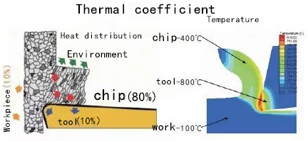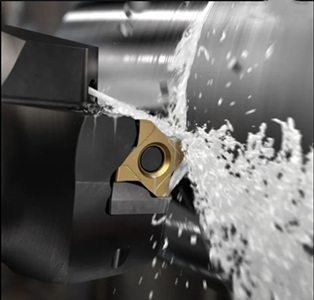
When cutting metal, temperatures up to 800 to 900 ℃ are generated in the cutting zone. In this cutting area, the cutting edge deforms and excises the workpiece material.
In continuous turning, heat is generated in a stable linear fashion. In contrast, the cutter teeth cut and cut work material intermittently, and the temperature of the cutting edge alternately rises and falls. The components of the machining system absorb the heat generated during metal cutting. Typically, 10% of the heat goes to the workpiece, 80% to the chip, and 10% to the tool. The best case scenario is that the chips carry away most of the heat, as high temperatures can shorten tool life and damage the parts being processed.

Different thermal conductivity of workpiece materials and other processing factors will have a significant impact on the heat distribution:
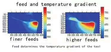
When machining the workpiece with poor thermal conductivity, the heat input to the tool will increase. Processing a material with higher hardness will generate more heat than processing a material with lower hardness. Higher cutting speeds increase heat generation, and higher feed increases the area of the cutting edge affected by high temperatures.
Heat generation, absorption and control are affected by the choice of tool contact arc, feed, cutting speed and cutting edge groove type in interrupted cutting conditions mainly based on milling.
Contact arc:
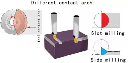
Due to the intermittent nature of the milling process, the cutter generates heat only during part of the machining time. The percentage of cutter cutting time is determined by the contact arc of the milling cutter, which is influenced by the radial cutting depth and tool diameter.
The contact arc is also different for different milling processes. In slot milling, the workpiece material surrounds half of the tool and the engagement arc is 100% of the tool diameter. Half of the cutting edge's processing time is spent cutting, so heat builds up quickly. In side milling, a relatively small part of the tool meshes with the workpiece, giving the cutting edge more opportunity to dissipate heat into the air.

Cutting speed:
In order to keep chip thickness and temperature in the cutting zone equal to the value when the tool was cutting at full length, the tool supplier developed a compensation factor to increase the cutting speed when the tool engagement percentage decreased.
From a thermal load perspective, the contact arc is small and the cutting time may not be sufficient to produce the minimum temperature required for maximum tool life. Increasing the cutting speed usually generates more heat, and the combination of smaller engagement arcs with higher cutting speeds helps to raise the cutting temperature to the desired level. The higher cutting speed reduces the time the cutting edge is in contact with the chip, thereby reducing the heat transferred to the tool. Overall, higher cutting speeds reduce machining time and increase productivity.
On the other hand, lower cutting speeds reduce machining temperatures. Too much heat is generated during machining and reducing the cutting speed can bring the temperature down to an acceptable level.
Cutting thickness:
The thickness of chips produced during milling changes as the cutting edge moves in and out of the workpiece. Therefore, tool suppliers use the concept of "average chip thickness" to calculate the tool feed to maintain the most efficient chip thickness.
Factors involved in determining the correct feed include the tool's contact arc or radial cutting depth and the tool cutting edge angle. The larger the mesh arc, the smaller the feed required to produce the ideal average chip thickness. Similarly, the smaller the tool engagement arc, the higher the feed required to obtain the same chip thickness. The cutting edge angle can also affect the feed requirements. When the cutting edge angle is 90°, the chip thickness is the largest. Therefore, in order to achieve the same average chip thickness, reducing the main cutting edge angle needs to increase the feed.

Slot of cutting edge :
The geometry of the milling cutter body and the cutting edge help control the heat load. The hardness of workpiece material and its surface condition determine the choice of tool rake Angle. Positive rake tools generate less cutting force and heat, while allowing for higher cutting speeds. However, positive rake cutters are weaker than negative rake cutters, which produce higher cutting forces and higher cutting temperatures.
The groove of the cutting edge can cause and control the cutting action and cutting force, thus affecting the generation of heat. The edge of the tool in contact with the workpiece can be chamfered, passivated or sharp. Chamfered or passivated edge strength is greater, resulting in more cutting force, more heat. Sharp edge can reduce cutting force and reduce machining temperature.
The chamfering behind the cutting edge is used to guide the chip. It can be either positive or negative chamfering. Positive chamfering also produces lower machining temperature, while negative chamfering design has higher strength and generates more heat.
The milling process is intermittent cutting and chip control characteristics of the milling cutter are usually not as important as they are in turning. Depending on the workpiece materials and engagement arcs involved, it may become important to determine the amount of energy required to form and guide chips. Narrow or forced chip breaker chip control grooves allow for immediate chip roll-up and greater cutting force and more heat. The more open chip control groove type produces lower cutting forces and lower machining temperatures, but may not be suitable for some combinations of workpiece materials and cutting parameters.
Cooling:
One way to control the heat generated in metal cutting is to control the application of coolant. Too high a temperature will lead to rapid wear or deformation of the cutting edge, so the heat must be controlled as soon as possible. In order to reduce the temperature effectively, the heat source must be cooled.

A variety of interrelated factors together form the load in metal cutting. In the process of processing, these factors will affect each other.
---EDITOR: Doris Hu
---POST: Doris Hu
<< :Application of CBN inserts in cutting chilled cast iron roll
<< :Application of superabrasive materials in machinery manufacturing
Diamond heat spreaders offer ultra-high thermal conductivity up to 2000 W/m·K, excellent electrical insulation, and outstanding chemical stability. Widely used in AI data centers, 5G/6G base stations, high-performance computing, aerospace, and power semiconductor modules, diamond thermal substrates significantly reduce chip junction temperature and enhance long-term device reliability.
Learn about wire drawing dies, essential tools in metal wire processing used to reduce wire diameters and improve surface quality. Discover the different types of dies (tungsten carbide, PCD, natural diamond, and CVD diamond) for various metals and applications, including their material properties, functions, and selection guidelines. Understand how to choose the right die for precise wire drawing, enhancing efficiency, quality, and cost-effectiveness in industries like power transmission, semiconductor packaging, and medical device manufacturing.
Add: Zhongyuan Rd, Zhongyuan District, Zhengzhou, 450001, Henan, China
Tel: +86 17700605088